Frequency response analysis
By using SL Palette, you can make Scideam and Simulink work together and perform a frequency response analysis.
The frequency response analysis analyzes the frequency characteristics, which are useful for judging the stability of a circuit.
For the analysis method, refer to Frequency response analysis.
How to run the simulation
Setting the simulation mode
To perform a frequency response analysis, select FrequencyResponseAnalysis from the simulation mode of the SCIDEAM block.
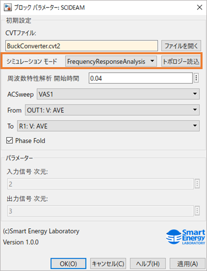
When you have changed the simulation mode, press the Apply button once to reflect the change in the model.
Setting the analysis start time of the frequency response analysis
A frequency response analysis is calculated correctly by performing it in a state where the system has reached the steady state.
Therefore, set the time at which the steady state is reached as a block parameter.
Info
Before performing a frequency response analysis, checking in advance with Transient the time at which the system sufficiently reaches the steady state, and setting that value to "Frequency response analysis start time", lets you perform the analysis smoothly.
Specifying the AC Sweep part and the input and output of the transfer function
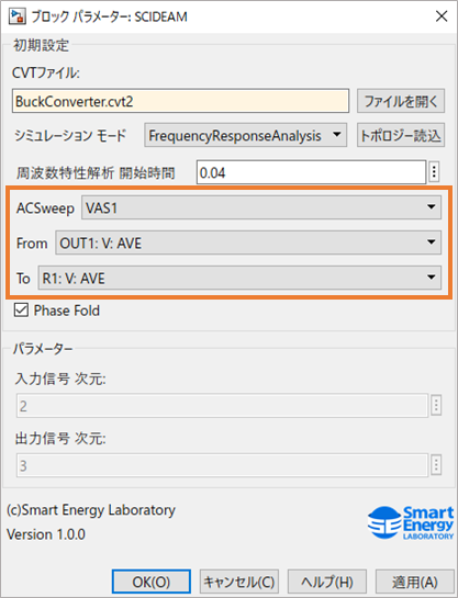
In a frequency response analysis, you need to specify the AC Sweep part placed in the Scideam circuit model, and the output variables used as the input and output of the transfer function.
By loading the CVT file, the symbol names of the AC Sweep parts in the circuit model and the output variables that are set are loaded into the SCIDEAM block as a list.
If you modify the CVT file from Scideam and the number or symbol names of the AC Sweep parts or the output variables are changed, you can reflect this by pressing the Load topology button.
When there has been a change, be sure to press Load topology to update the information inside the SCIDEAM block.
If it is not reflected properly, press the Apply button once and then try again.
Setting the input signal dimension and the output signal dimension
For Input signal dimension and Output signal dimension, the values set in the SLC script file are reflected automatically by loading the circuit file.
On the Simulink model side, make the number of dimensions of the input and output signals the same as these values.
If you modify the CVT file from Scideam and the number of input signal dimensions or output signal dimensions is changed,
you can reflect this by pressing the Load topology button.
When you have changed the number of input signal dimensions or output signal dimensions, be sure to press Load topology.
If it is not reflected properly, press the Apply button once and then try again.
Setting the simulation time
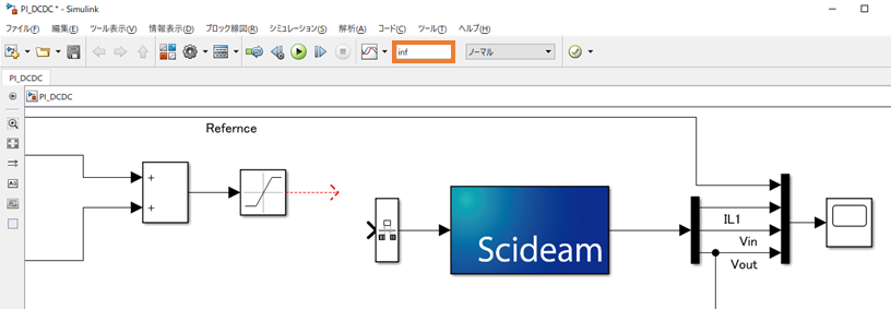
In a frequency response analysis, the simulation time is set as infinite time.
Therefore, please set inf as the simulation time of Simulink.
The analysis finishes automatically as soon as the result is obtained.
Placing the SCIDEAM BODE block
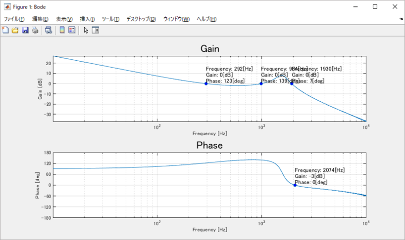
The result of the frequency response analysis can be checked in a Bode plot.
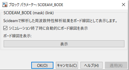
To check it in a Bode plot, you need to place a SCIDEAM BODE block on the Simulink model.
By checking the option to automatically display the Bode plot at the end of the simulation, you can check the result immediately after the simulation finishes.
Checking the simulation results
The simulation results can be checked in a Bode plot from the SCIDEAM BODE block.
The detailed results are also output to the MATLAB workspace.
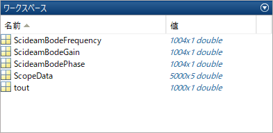
In the Bode plot you can check waveforms such as the following.
When the frequency response results are not obtained properly
The frequency response analysis performed in cooperation with Simulink uses the frequency response feature of Scideam internally.
Depending on the system to be analyzed, this feature may not give accurate results.
To obtain accurate results, refer to Frequency response analysis and correct the parameters or the model.