Troubleshooting for state over detection and state undetermined detection
State over detection and state undetermined detection occur for multiple reasons, so a countermeasure that matches the cause is required.
In many cases they are resolved by the countermeasures shown below, but state detection may involve several problems at the same time,
and a countermeasure may cause another problem, so we recommend checking one countermeasure at a time.
How to check the states
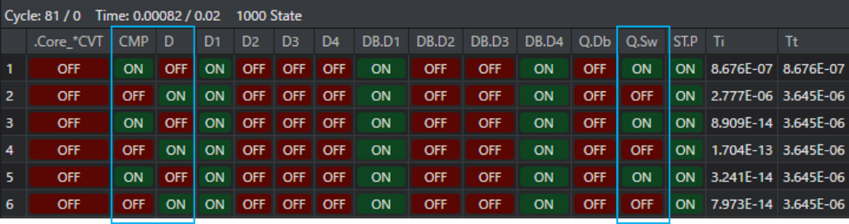
When state over detection or state undetermined detection occurs, the State Viewer starts up and you can check the state of the parts for each cycle.
State over detection and state undetermined detection mainly occur because a part repeats the ON state and the OFF state. When a problem occurs, first check the State Viewer and pay attention to the parts whose ON state and OFF state are repeated.
Example
For example, in the following case the states of the comparator CMP, the diode D, and the switch Q cannot be determined.
First check the settings of these parts and the surrounding circuit.
For the definition of a state in Scideam, please check Simulation engine: About states.
Typical examples of state over detection and how to solve them
Example 1
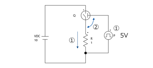
When the switch turns on, because it is an ideal switch the gate voltage is lifted up in a step and it can no longer turn on. In such a case, a contradiction occurs in the circuit operation and the operation becomes indeterminate.
Example 2
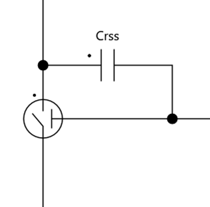
When the switch turns on, because it is an ideal switch the drain-gate voltage drops in a step and it can no longer turn on. In such a case, a contradiction occurs in the circuit operation and the operation becomes indeterminate.
Tips
Example 2 also occurs when Ciss, Coss, and Crss are implemented on an ideal part.
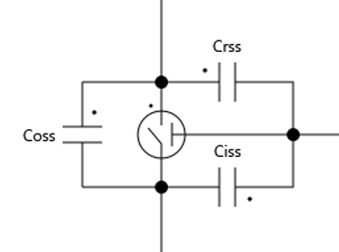
In this case, because it is an ideal switch, the voltage and current of each capacitor change in a step,
each of them loops, and the voltage and current become indeterminate.
How to solve
-
Correct the model so that a contradiction does not occur and the solution does not become indeterminate
If it is a circuit or logic in which a contradiction inevitably occurs, using hysteresis or a delay by an RC filter makes it easier to determine the states. -
Give appropriate initial values
If it is a circuit in which the initial conditions are not determined and become indeterminate, give appropriate initial voltages and currents to C and L.
Examples of solutions for each part
Circuit configuration
- Simplify or divide the circuit according to the purpose of the simulation.
- Try to reduce the number of parts that have states and the number of LCs as much as possible.
- For a feedback circuit without I control, add a small delay time circuit (such as an RC circuit with a small time constant).
Resistance
- If you have entered an extremely small value, set it again using R=1mΩ as a guide.
- When they are connected in series or in parallel, combine them into one if there is no problem in doing so.
Capacitor
- If you have entered an extremely small value, set it again using C=1pF as a guide.
- If there are Cs in parallel, either combine them or turn ESR on.
Inductor
- If you have entered an extremely small value, set it again using L=1nH as a guide.
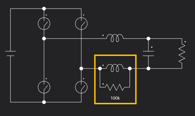
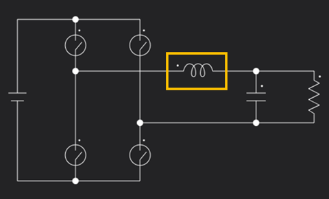
- If they are connected in series, try the following countermeasures.
- Countermeasure 1: Connect a sufficiently large resistance in parallel
- Countermeasure 2: Combine them into a single L
Diode
- Set the OFF resistance to about 100kΩ.
- Set the stored charge to 0.
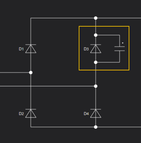
Tips
If diodes with the same parameters are connected symmetrically, set the OFF resistance of one of them to half.
Ideal Switch
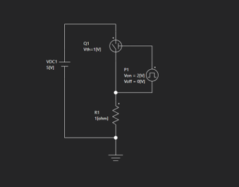
- Avoid a drive configuration in which on and off cannot be determined.
- In the case of the figure below, the impedances on the source side are different, the state of the switch switches continuously, and state detection occurs.
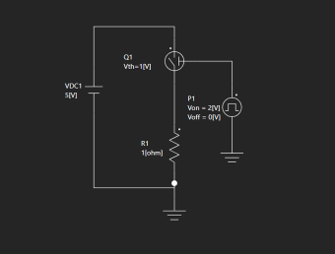
It can be resolved by correcting it as shown in the figure below.
- Please do not attach Crss externally.
- If the body diode does not conduct, turn the setting off.
- Set the gate hysteresis voltage. Use about 1% of the gate voltage as a guide for the setting value.
- Connect a C of about 100pF to 1nF between the drain and the source.
Note
If there are multiple switches, do not connect it to all of the switches; keep it to the minimum at which state detection no longer occurs.
If there is a dead time, be sure to connect a C.
Comparator
- Set the hysteresis voltage to about 1% of the input voltage.
Note
Be sure to set it when comparing an analog input and a digital input.
MOSFETs and transistors used as amplifying parts
- When you use them as amplifying parts, make sure they do not perform switching operation.
- When you make them perform switching operation, please use an ideal switch or a detail switch.
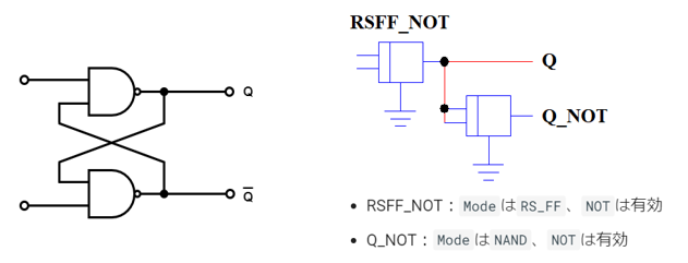
Logic parts
- As an alternative circuit, use a cross-coupled NAND circuit.
If the problem is not resolved by the above countermeasures
Note
If the problem is still not resolved after the above, please contact us through the inquiry form.
Please note the following in advance.
- We may ask you for details about the steps you have taken.
- Specific parameter settings and modeling are provided as a paid service.