About the part models
Basic operations of the part models
Displaying the part models
The list of part models is displayed in the Palette window.
The Palette window can be opened by clicking Palette from View in the menu bar.
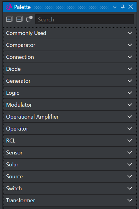
Placing the part models
Part models can be placed by dragging and dropping them from the Palette window to the circuit editor.
Right-click menu of a part
The part menu is displayed by selecting a part and right-clicking.
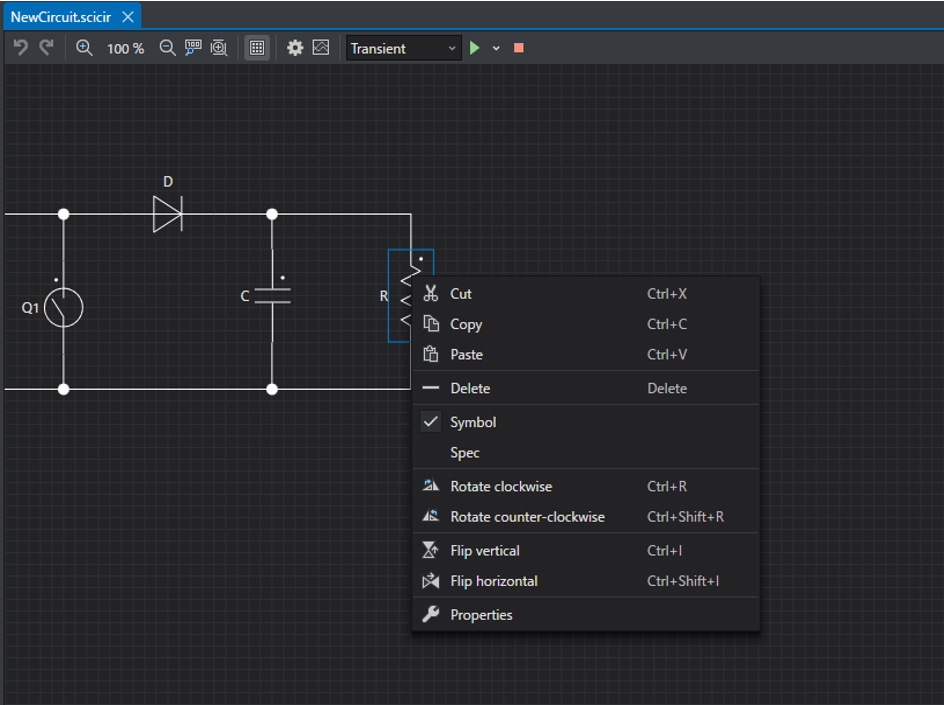
| Feature | Description |
|---|---|
| Cut | Cuts the selected part. In the default settings, Ctrl + X is registered as the shortcut key. |
| Copy | Copies the selected part to the clipboard. In the default settings, Ctrl + C is registered as the shortcut key. |
| Paste | Pastes the part copied to the clipboard. In the default settings, Ctrl + V is registered as the shortcut key. |
| Delete | Deletes the selected part. In the default settings, Del is registered as the shortcut key. |
| Symbol | Displays the symbol name of the selected part. |
| Spec | Displays the parameter values of the selected part. |
| Rotate right | Rotates the selected part 90° to the right. In the default settings, Ctrl + R is registered as the shortcut key. |
| Rotate left | Rotates the selected part 90° to the left. In the default settings, Ctrl + Shift + R is registered as the shortcut key. |
| Flip vertically | Flips the selected part about the vertical axis. In the default settings, Ctrl + I is registered as the shortcut key. |
| Flip horizontally | Flips the selected part about the horizontal axis. In the default settings, Ctrl + Shift + I is registered as the shortcut key. |
| Properties | Opens the Inspector window for configuring the properties of the part. |
Changing the part parameters
Once you have finished placing the parts, next let's change the parameters of the parts.
The parameters of a part are changed in the Inspector window.
The Inspector window is displayed by double-clicking a part.
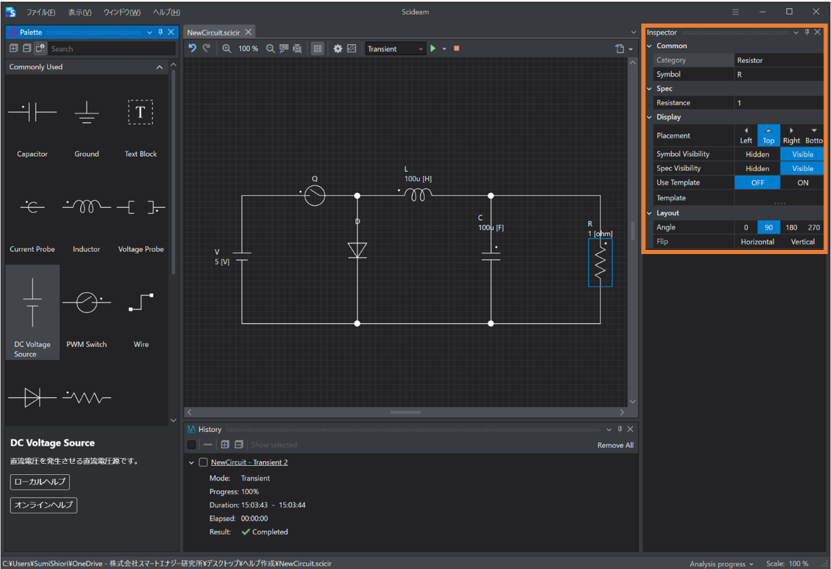
The symbol name of a part can be changed from Symbol name on the Common tab.
The element values of a part can be changed from the Spec tab.
Input restrictions on the part parameters
Several input restrictions are set on the part parameters.
As a restriction common to all parts, the symbol name of a part must be unique.
For the other input restrictions, refer to the page of each part model.
Unit system
Numerical parameters in Scideam are displayed as a combination of a number and an exponent symbol such as m or k, with a few exceptions such as the duty ratio, and the units are the base units of the MKSA unit system.
When entering a numerical value, you can enter either a number alone or a combination of a number and an exponent symbol.
Example
For example, in the case of an inductance, to express 1.5mH you can enter either a number alone, such as the decimal expression 0.0015 or the exponential expression 1.5e-3, or a combination of a number and an exponent symbol, such as 1.5m.
The formats of the exponential expression are
(mantissa)e(sign)(exponent)
(mantissa)E(sign)(exponent)
0.0047 = 4.7e-3
95200 = 9.52e4
When entering it, you can omit the
+ when the sign is positive, but be sure to add - when it is negative. The exponent symbols that can be used are as follows.
| Symbol | Number of digits |
|---|---|
| p | 1.00e-12 |
| n | 1.00e-09 |
| u | 1.00e-06 |
| m | 1.00e-03 |
| k | 1.00e+03 |
| M | 1.00e+06 |
| G | 1.00e+09 |
| T | 1.00e+12 |
Caution
The exponent symbol that represents 1.0e-6 is the letter u (u), not μ (micro).
Note
Exponent symbols such as m and k cannot be used in Transitions of Palse and PWM Switch.
Please set them with a number or an exponential expression using e.