Push-Pull DC-DC Converter
Overview
A push-pull DC-DC converter turns on two switches alternately to drive the two primary windings of a transformer in turn. As an isolated power supply, it is used in a wide range of applications, such as medium- to high-power supply circuits and voltage conversion stages that use a transformer.
Applications
- Building block of isolated DC/DC converters
- Medium- to high-power supply circuits
- Voltage conversion stages that use a transformer
How to Simulate a Push-Pull DC-DC Converter
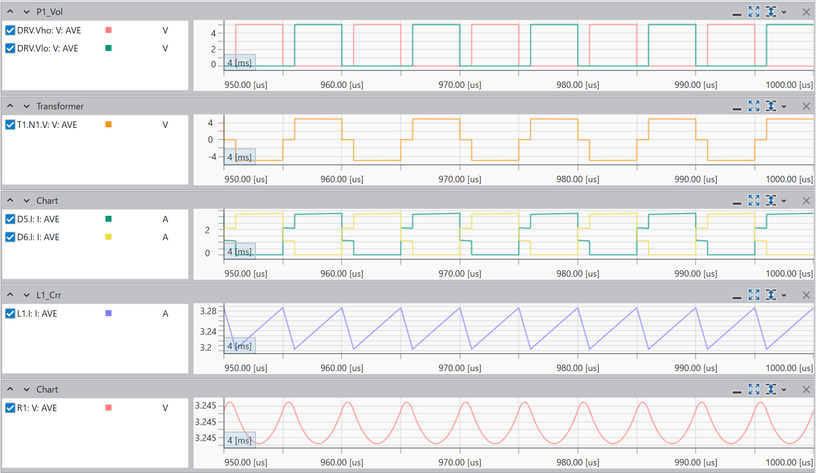
Open the sample circuit "PushPull.scicir" in Scideam and run a Transient(Full) analysis to check the output voltage waveform of the push-pull DC-DC converter right away.
Without building real hardware, you can observe the two switches operating alternately and the resulting output waveform directly in the simulation.
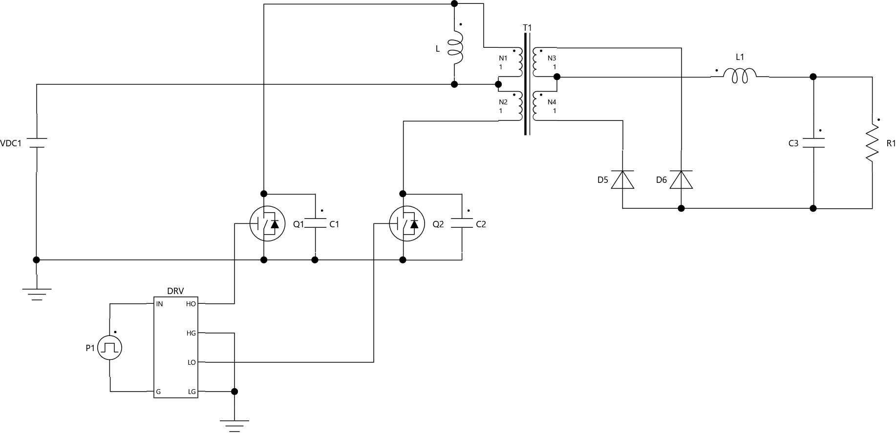
Example
The circuit files can be downloaded from the sample circuit top page.
Sample circuit:
Scideam/circuit_library/push_pull/PushPull.scicir
Circuit Parameters
| Item | Value |
|---|---|
| Input voltage VDC1 | 5 V |
| Switching frequency | 100 kHz |
| Duty ratio | 0.5 |
| Inductor L | 10 μH |
| Transformer turns ratio N1:N2:N3:N4 | 1:1:1:1 |
| Inductor L1 | 47 μH |
| Output capacitor C3 | 100 μF |
| Output load R1 | 1 Ω |
Simulation Results
Run the simulation with a Transient(Full) analysis, with fast forward set to ON, End Time set to 5 ms, and display interval set to 50 us. With these settings, the analysis is fast-forwarded to near the steady state and the interval you want to check is displayed.