Detail Switch Setting
Feature description
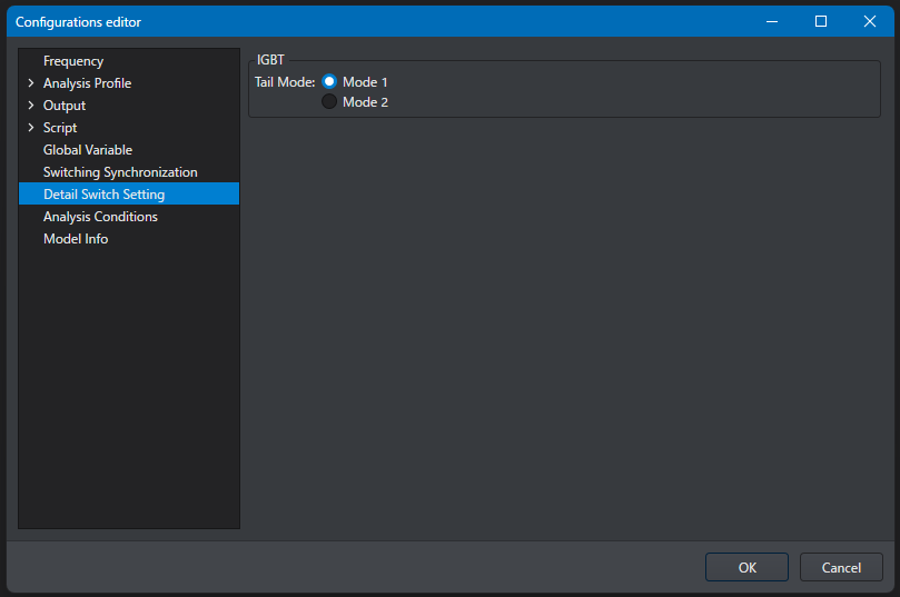
In Detail Switch Setting you can change the settings related to the detail switch model of Scideam.
Detail Switch Setting can be opened from the config editor.
FET
Enabling the feedback capacitance Crss of the internal block
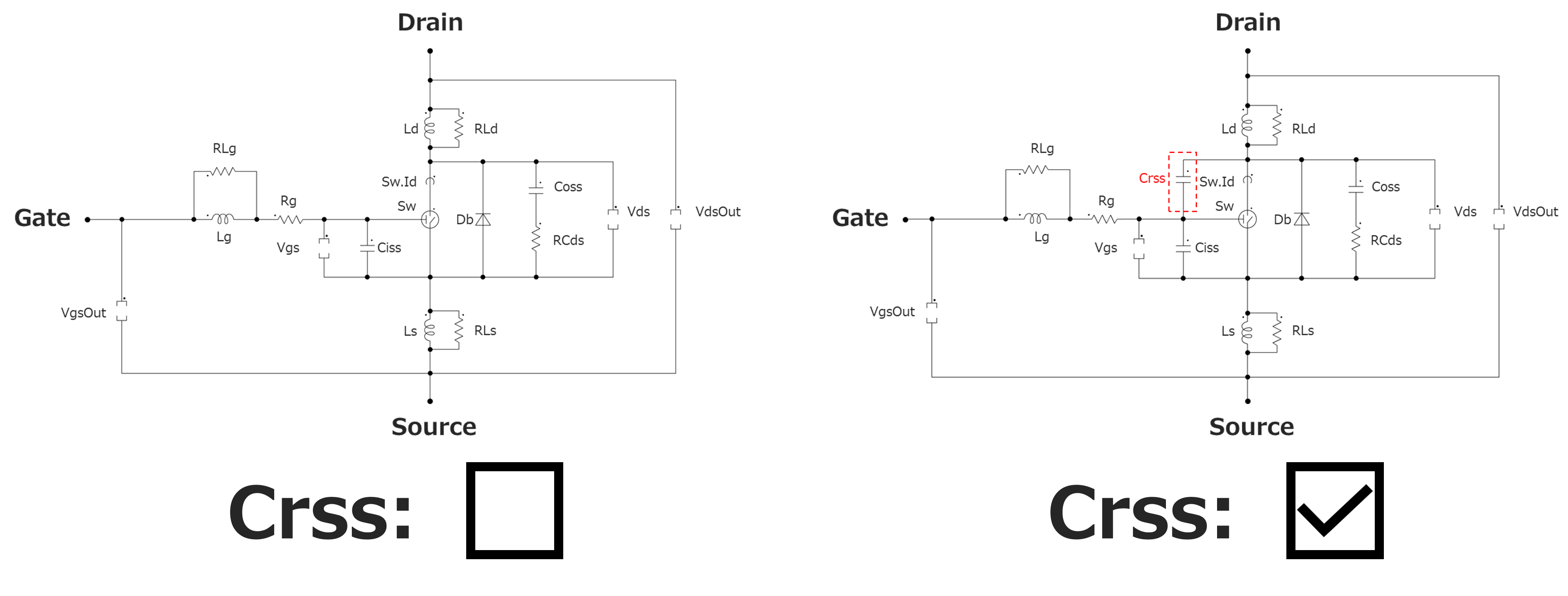
By checking this, the internal block of the FET part is treated as a circuit that includes the feedback capacitance Crss.
The internal circuit is as shown in the figure below.
In versions v2.16 and later, this setting cannot be selected and is always enabled.
-
When Crss is unchecked
Crss becomes a model that is not included inside the part, and in order to adjust the slope of the drain current, it becomes a model in which the input capacitance of the FET increases due to the Miller effect in the active region.
Therefore, Crss is not configured as a part in the internal block, and a high-speed simulation can be performed. -
When Crss is checked
Crss is included inside the part, and the Miller effect occurs in the active region. The capacitance of Crss is set automatically by the part parameters and is changed dynamically by the voltage and current of the switch.
Therefore the analysis time may become longer, but a detailed simulation can be performed.
Note
Crss is applied only during a detail analysis.
IGBT
Enabling the feedback capacitance Cres of the internal block
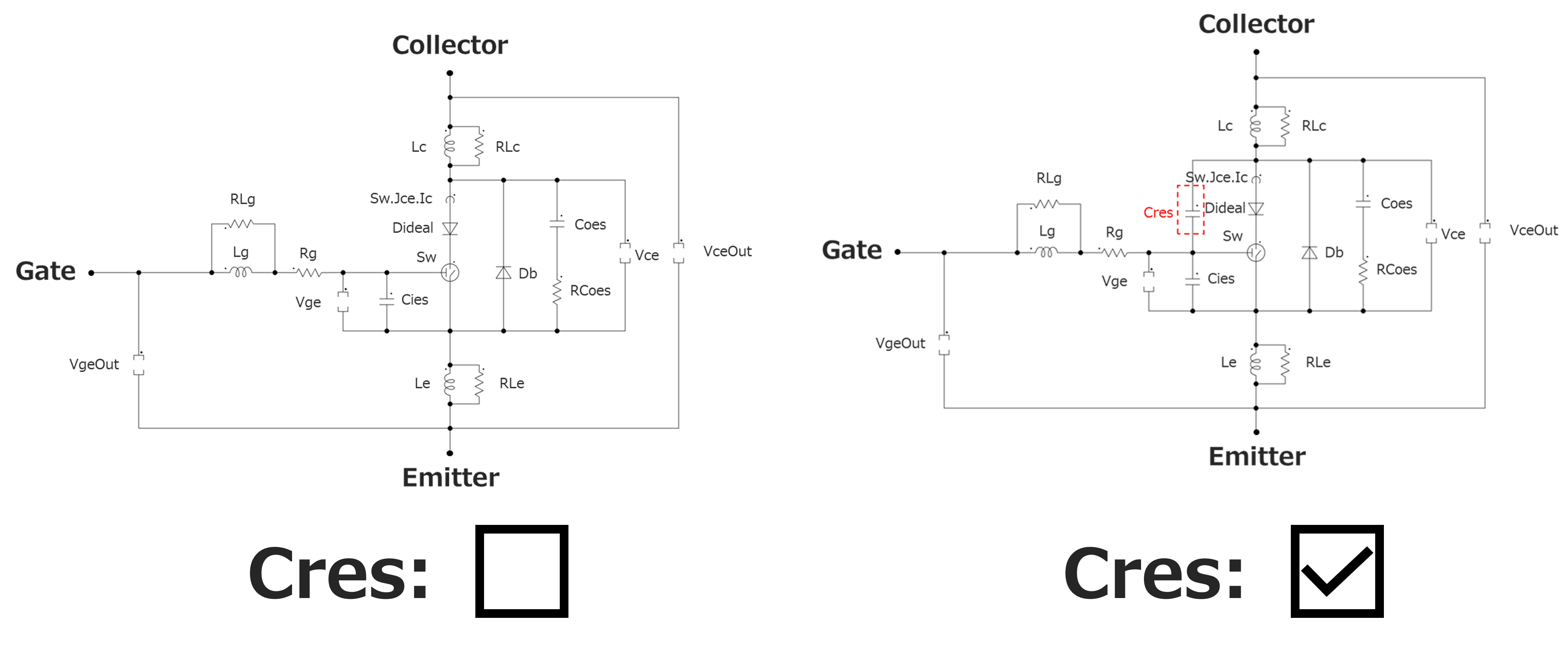
By checking this, the internal block of the IGBT part is treated as a circuit that includes the feedback capacitance Cres.
The internal circuit changes as shown in the figure below.
In versions v2.16 and later, this setting cannot be selected and is always enabled.
-
When Cres is unchecked
Cres becomes a model that is not included inside the part.
Therefore, a high-speed simulation can be performed. -
When Cres is checked
Cres is included inside the part, and the Miller effect occurs in the active region. The capacitance of Cres is set automatically by the part parameters and is changed dynamically by the voltage and current of the switch.
Therefore the analysis time may become longer, but a detailed simulation can be performed.
Note
Cres is applied only during a detail analysis.
Note
The parameter Reverse Transfer Capacitance(Cres) at 20[V] of the IGBT part is a parameter that is applied only when Cres is checked.
Selecting the tail current model
The IGBT part has two analysis modes for the period during which the tail current at turn-off is flowing, and you can switch between them in Detail Switch Setting.
Modes in the detail loss analysis
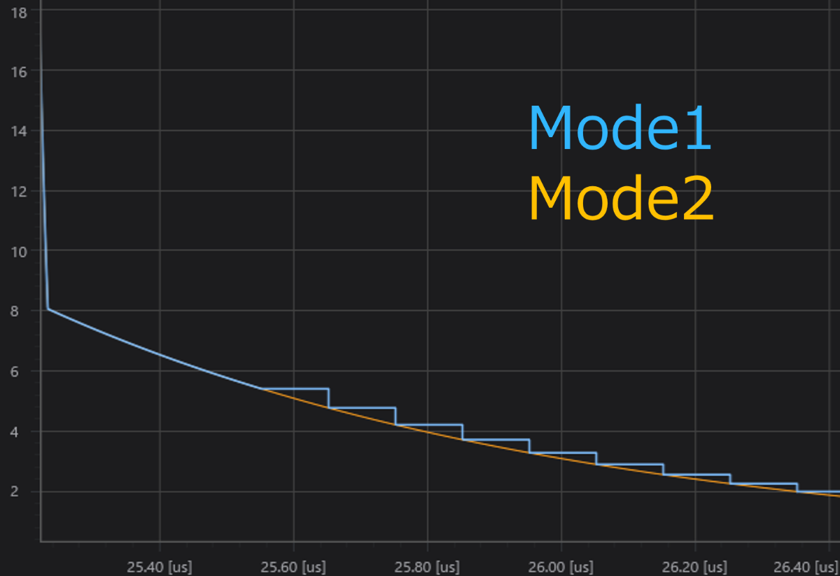
Mode1 is a mode with a fast analysis speed, and this mode is selected by default.
Mode1 calculates the loss including the tail current analytically (with expressions), using the values set as the tail parameters.
Because the loss is not calculated from a waveform analysis, the analysis is performed at high speed with sufficient accuracy, but the accuracy is slightly lower compared with Mode2.
Mode2 is a mode that calculates the loss from the detailed waveform.
Normally, because the tail period is very long, the analysis time also becomes long, but the accuracy is higher.
Modes in the Transient analysis (Full, Detail)
Mode1 takes a long analysis step time (step width) and calculates and outputs a rough waveform.
Because the number of analysis steps decreases, the analysis can be performed at high speed, but the output waveform becomes staircase-shaped.
This is a mode intended for use in performing a high-speed analysis to grasp the outline.
Mode2 performs a detailed waveform analysis according to the algorithm of Scideam without adjusting the analysis step time, until the tail current becomes 10% of that at the start of the tail characteristics.
Normally, because the tail period is very long, the analysis time also becomes long, but a detailed waveform can be output.