Gate Driver1
Appearance
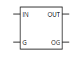
Description
Gate Driver1 is a single-output gate driver part that drives a switch.
The dead time can be set freely.
The operating period of this part is determined by the main frequency or a sub frequency.
If you want to drive the high-side and low-side switches at the same time, please use the gate driver.
The terminals of the part have the following meanings.
| Parameter | Description |
|---|---|
| IN | Input voltage |
| G | Input ground |
| OUT | Output |
| OG | Output ground |
The ground terminals G and OG are each isolated, and the input and output waveforms are as follows.
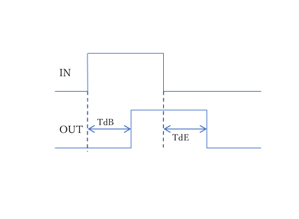
The output pulse cannot be set beyond the operating period.
Also, it operates on the assumption that the input pulse at the start of the analysis starts from 0.
Note
Please use the gate driver with one pulse within the operating period.
The operation when there are two or more pulses is indeterminate.
Note
We recommend that the input IN start from 0.
If IN starts from a positive value, the operation of the first period becomes indeterminate.
Note
Please set the parameters so that the width of the input pulse is greater than or equal to the dead time.
If the pulse width is less than or equal to the dead time, the operation becomes indeterminate.
Spec
| Parameter | Description | Parameter name |
|---|---|---|
| ON Voltage | Output voltage | Von |
| OFF Voltage | Output voltage | Voff |
| Threshold Voltage | Gate threshold voltage | Vth |
| Start Delay Time | Start delay time | TdB |
| End Delay Time | End delay time | TdE |
Output variables
| Parameter | Description | Output argument |
|---|---|---|
| Input Voltage | Input voltage | symbol name.Vi |
| Output Voltage | Output voltage | symbol name.Vo |