Three-phase permanent magnet synchronous motor [PMSM]
Appearance
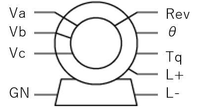
Description
Info
Required option: Motor Palette
Frequency settings
Because a motor model is a nonlinear part, please set the main frequency and the sub frequency with attention to the following point.
Main frequency > sub frequency
As the values to set, we generally recommend a factor of about 10 to 20 times.
For example, if the switching frequency is 10kHz, set
Main frequency = 100kHz
Sub frequency = 10kHz
and register the oscillation source of the switch to the sub frequency.
Three-phase permanent magnet synchronous motor [PMSM] is a three-phase permanent magnet synchronous motor.
Three-phase permanent magnet synchronous motor [PMSM] performs a DQ transformation internally in order to improve the analysis speed.
Therefore, the inputs Va, Vb, and Vc cannot be used unless they are in a three-phase balanced state.
The torque is calculated by the following expression.
Tm : Torque
Np : Number of poles
iq, id : q-axis current, d-axis current
Lq, Ld : Equivalent q-axis inductance, equivalent d-axis inductance
Kemf : Back voltage constant
Terminals
| Terminal | Name | Description |
|---|---|---|
| Va,Vb,Vc | Three-phase input voltage terminals | Input the voltage [V] of the a phase, b phase, and c phase. |
| GN | Equivalent ground terminal | This is a virtual terminal on the motor model, and must always be connected to the ground on the inverter side. This terminal is not the neutral point terminal of an actual machine. A terminal corresponding to the neutral point terminal of an actual machine does not exist in this motor model. |
| Rev | Rotation speed output terminal | The rotation speed in rpm is converted to a voltage [V] and output between this terminal and the GND terminal inside the motor. |
| θ | Cumulative rotation angle output terminal | The rotation angle [rad] accumulated from the start of rotation, including the initial value, is converted to a voltage [V] and output between this terminal and the GND terminal inside the motor. |
| Tq | Torque output terminal | The mechanical torque [N*m] is converted to a voltage [V] and output between this terminal and the GND terminal inside the motor. |
| L+ | Load terminal | This is the terminal for connecting a load. The load is connected between this terminal and the GND terminal inside the motor. |
| L- | Ground terminal | This is the ground terminal inside the motor. It is independent of the ground on the inverter side, so it is not always necessary to connect this ground to the inverter ground. |
When building a load freely
When you build the load connected to the load terminal yourself instead of using a predefined load, replace it as follows and connect it in parallel.
- Torque ⇒ current source
- Moment of inertia ⇒ capacitor
- Reciprocal of the viscosity constant ⇒ resistance
Spec
| Parameter | Description | Parameter name |
|---|---|---|
| Moment of Inertia[kg*m^2] | Moment of inertia | IM |
| Initial Rotor Angle[deg] | Initial rotation angle | THm |
| Stator Resistance[Ω] | Winding resistance of the stator | Rs |
| Inductance D[H] | Equivalent d-axis inductance | Ld |
| Inductance Q[H] | Equivalent q-axis inductance | Lq |
| Pole | Number of poles | Np |
| Back Voltage Constant[V/(rad/s)] | Back voltage constant | Kemf |
| Viscosity[kg*m^2/s] | Viscosity constant | VC |
Output variables
| Parameter | Description | Output argument |
|---|---|---|
| - | - | - |